Control and valve drivers
Diinef's control architecture consists of two PCB's, a Master/Control PCB and a Slave/Driver PCB. The PCB's communicate over a fast 100 Mbit Realtime PowerLink bus and up to 800 solenoids can be controlled with 1ms sample time on the same bus.
The digital valve Driver can be applied by itself for valve control and act as a master node for valve control by other Driver cards. By adding a Master card more sensor inputs are made available, and more processing power can be dedicated for application control. The Driver can then be focused on valve activation and monitoring.
Slave/Driver
Features
-
Up to 14 valve drivers pr. PCB
-
Redundant power supply (range 17-57.6 Vdc)
-
Redundant 100 Mbit Realtime PowerLink bus
-
PWM controlled valve driver with current feedback
-
Current suppressing circuit for fast decharge
-
TI Hercules SIL3 MCU
-
CAN and SPI service port
-
Bootloader for network update of software
-
1 x Multi-colored LED status light
-
1 x SSI encoder interface
Activation
-
24V/1A nominal (3A peak)
-
12V/2A (optional)
-
From 20-25 ms shifting time*
Connections
-
Power: 2 x 4 pin M12
-
Network: 2 x 4 pin M12
-
Service: 1 x 8 pin M12
-
Solenoid: 3 pin connector
-
Encoder: JST ZHR-8 connector
Master/Control
Features
-
TI Hercules SIL3 MCU
-
Redundant 100 Mbit Realtime PowerLink bus
-
2 x analog 12-24 Vdc (optocoupler interface) for eg. EMS signalling
-
4 x ratiometric transducer input
Connections
-
1 x 4 pin SPT-THR (EMS signalling)
-
4 x 5 Vdc ratiometric (0.5 - 4.5 Vdc) 4 pin connectors
-
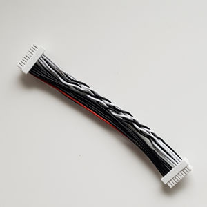
1 x 20 pin JST ZPD connector for power, bus and service signals


